
OSI Ford 2,3TS 1968
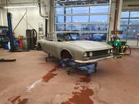
This OSI Ford has been disassembled and paint stripped at Carblast in Stuttgart.
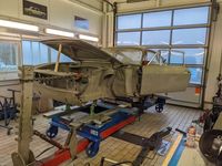
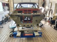
After multiple measurements it has now been fixed to a Cellete bench. and first missing sheet metal parts will be manufactured. The coming steps of this restauration projekt will be shown here.
** Clicking the picture or text will lead you to a photo collection **
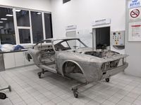
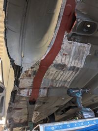
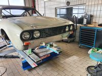
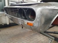
State after paint strippung
Unfortunately the real status of the body shell can only be determined after paint stripping. The whole picture of corrosion damages and impacts of collisions can be seen now!
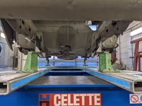
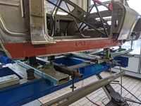
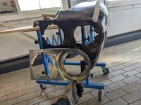
Adaption to a Celette anchoring system
Based on a VW Golf 2 straightening set, an individual adapter set has been manufactured to fix the body shell at its relevant fixing points (engine bay and rear axle).
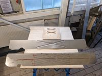
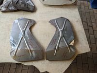
Manufacture of A Pillar Reinforcements
The A Pillar Reinforcements are manually produced based on measurements and pictures from an untouched body. Tools and gages are handmade as well. The result is quite close to the original parts.
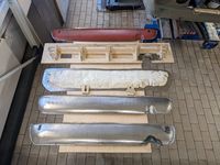
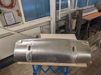
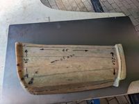
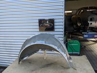
Manufacture of Rear Lower Center Panel
By many little steps this panel gets manufactred by hand. First a wooden gauge is made along an original piece (thanks to Thomas). After stretching, shrinking, hammering, welding and smoothening, the result is a panel very close to the ones made back in time.
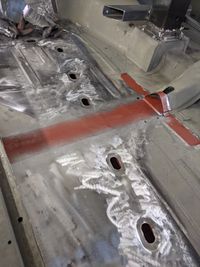
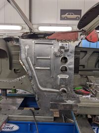
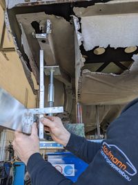
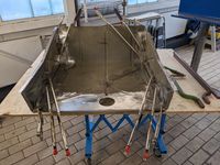
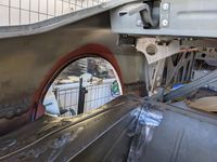
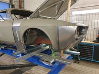
Straightening before reconstruction
Straightening work has to be done, to understand and repair deformation to the structure by a former front crash impact. Important: do it now or never, because straightening is almost impossible after major cutting of structure. To support the center structure a 'Support Tower' has been implemented with connection to the gage. Everything is now ready to start the reconstruction in the area of left hand side A Pillar.
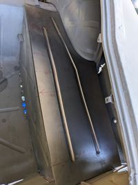
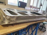
Manufacture of Front Lower Center Panel
The existing Front Panel has huge deformations due to the former front crash. To reproduce this rather big panel again a detailed gage has been made upfront to be able to check contures during the formin.g process. The part includes openings for the front bumper brackets as well as the retainers for the turn lights.
Manufacture of Back Panel Inner
First use of my brand new special made roller tooling for the refurbished bead roller. This back panel has some minor but important details, such as the draft of 10mm on 1200mm width. Also the little nodges have been incorperated which insure the correct position of the back panel. Final trimming will be done during the positioning of the complete rear structure.
Partially Replacement of Front Floor, Main Member and Dash
Parts have been saved from an 1969 20M. After disassembling the parts have been sand blasted and coated. Some weld flanges have been replaced to allow Resistand Spot Welding instead of MIG. An impressive 1,5m long gas welding line has been executed without any overlapping of paerts to get the floor into the body. Nearly invisible after straightening and grinding.
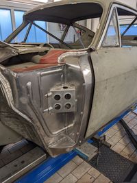
Manufacture of A Pillar Inner
The A PLR Inner is the central structural part in that part of the body, connected to almost everything. From the rest of the original structure, pictures and sketches the design needs to be established. Location and size of beads are crucial. Almost every tool has been used to make the parts as original and functional as possible: bead roller, bender, hydraulic press, stretcher, sandbag and lots of different hand tools. For the majority of joining a weld gun has been used.
Measurement and reinforcement of rear structure
Beofore starting to work on the rear part of the structure more measures are done and additional reinforcements are added. Especially significant height points require accurate measures. S`Data has been retrieved from the works drawing and for comparison a 100% untouched OSI has been measured (Thanks to Andreas!!)
Manufacture of Trunk Floor Panels
Even these relatively simple panels require the use of the bead roller, sheet metal bender and a simple wooden mold to get an accurate flange to the wheel house inner. Final trimming and form will be done, when the whole area will be fixed and arranged.
Manufacture of Body Side Rear Lower Inner and Outer
Existing GFK molds and a wooden gage are of great help during this manufacturing process. Thanks to OSI IG AGAIN!! Although quite precise a lot of adjustments, measurements and corrections are necessary to get to a satisfying result, which is matching the original shape as good as possible. Every part is made of DC04 Deep Draw quality sheet metal with an 0,8mm thickness.
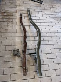
Repair of mid floor and rear main beam
Floor panel and main beam come from the same 20M and need a few hours of repair and straightening before matching the requirements of our OSI project. Main beam needs to be shortened to the OSI measures and also needs to get rid of an extra chassis joint. Later on the rear left wheel house inner and outer will be replaced due to corrosion.
Repair of rocker (inner/outer)
The OSI Rocker panel is surely one of the most komplex panels on that project. If the target is a maximimum of original radii and form, it is not possible to use any P5/P7 cary over panels or simple bended parts. Curvature is given by the reuse of the upper portion of the exiting rocker and a hand bended lower part joined by a 1700mm long gas welding seam. The rocker inner again comes from a 20M. Thanks again to Andreas and his untouched OSI, which delivered the measures to rebuild the lower rocker section
Repair of spare wheel well
The spare wheel well has been disassambled and got repaired instead of a complete new build. This keeps more of the orginin structure in place. Long gas welding seams and a lot of spot welds lead to a sufficient result. Now almost 80% of the rear structure is ready to be finished.
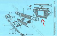
Modification Front End Cross Member from 20M to OSI
The OSI part is mainly made of modified 20M serial parts. The 20M front end plate is cutted into pieces, cutted to the correct width and the section is closed by small handmade panels. Lamp pots and lower cross beam need to be taken off and the side of the panel is cut back. A Z profile is connecting the upper cross member and the radiator frame. Final setting needs to be done with complete front end, grill, fenders, bumper and headlamps.
Manufacture of front whell house closing panel
This is a 100% copy of original panels (thanks to Knut!!). In an ideal case, the panels will be matched to the existing car to ensure a very good mating to the fender. This allows a proper sealing functing and does no harm to the fender inner treatment.
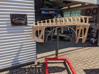
Development of a Fender Gauge
Due to a lucky perfect match situation we got our hands on a orginal sparepart Fender LHS, ordered and delivered 45 years ago and never used. Many thanks to Knut, who bought this part as a young man for his dream car these days at Ford in Cologne and today gives us this unique possibility to produce a gauge, that allows precise reproduction of sheet metal Fender parts.
Reproduction Lamp Can LHS
By using parts of the new fender gauge and a special gauge extension the Lamp Can LHS is produced. The gauge extension will help later on to get the body tin into shape. This process has also been used in the OSI factory.
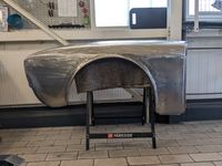
Rebuild Fender LHS
Based on the NOS spare part fender each surface ist buil seperately to be joint on the wooden gauge later on. In lots of hours a dimensional accurate handmade copy is made, that is not available on the market. As in former times most of the joints and transitions to other areas will be finalized by tinning after final fixing.
Finalization Wheelhouse and Rear Quarter
The rear wheel house is taken off and will be replaced by an equal P7 part. All connecting areas are rebuild and repaired. Taking off the wheel house gives room for the weld gun to join rear main beam, spare wheel pan and boot floor. The areas with poor access get an appropriate priming before the final assembly.
Rebuild A PLR Assy
The position of the A PLR needs a good attention, as it is influencing a lot of main measures for fit and finish. 4 new parts have been made and a lot more have been repaired in that area. After lots of measurements, research and adjustments the final joining contains: A Pillar Inner/Outer, Rocker Inner/Outer, A PLR Closing Panel, A PLR Reinforcement, Windscreen Beam and Fender Connection Panel. The result is another milestone on the way to the final body rebuild.
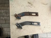
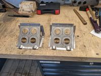
Reproduction Rear Bumper Bracket
First of all a steel tool is made to allow the flanging of the 2,5mm DC01 steel sheet metal. Total 4 parts are the joind with the help of a simple welding gauge. Both LHS and RHS are made from scratch for this 0800.
Repair of Body Side Outer RHS
As on the left hand side we now start to repair the Bodyside right hand side by forming the wheel arch inner and outer. The existing wheel arch flanges are full of corrosion but still in place, which is now a kind of gauge for the manual forming process. Before starting to take the structure apart front lower part of the bodyside is reproduced together with the rear part of the rocker, trying to match the existing structure as precise as possible. The formerly made rear lower, which was made to gauge, is also finalized on the existing structure, to match the original as good as possible. The result is a satisfying measurable placed wheel arch, matching the original and the measures on left hand side arch as well.
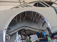
Remove and Repair of Wheel House Inner and Outer
As on the left side the wheel house inner and outer is removed kompletely. This saves a lot of time for the repair and replacement of lots of significant areas of that part. Other that on the LHS there is no need for a new part, as the damage ist far less. But nevertheless, a number of small pieces are made to get to all needed flanges for the origin welding process. After reaasembly there is a smooth and nice picture of the wheel arch crown!
Replacement of Main Beam Rear Right
Due to massive corrosion damages, the rear beam RHS needs to be replaced as well. Again a P5 serves this part, which needs a few modifications in the rear part. Due to the disassembled Wheel house, most of the joints can be executed by resistance spot weldig as on the original process. During the exchange of the beam the manual reproduced trunk floor pan is assembled and a part of the rear floor behind the heel kick is replaced as well.
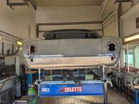
Finalization of Backpanel Area
Another hige Milestone is now achieved by assembling the back panel, that has been manufactured right at the beginning of the project. The body is now finished from B PLR backwards. Of course the back panel cavity is covered with an active primer and weld flanges with a special weld primer (INOX). Next step is A PLR and Fender RHS.
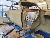
Finalization A PLR RHS
Next huge milestone towards finalization of welding steps. During this step the album shows manufacture and/or installation of: rocker lower, rocker front, rocker inner extension, piece, A pillar inner, A piller closing panel, A pillar reinforcement, trough outer, trough filler piece. The following parts have been repaired and installed: Front floor, dash outer, rocker inner, seat reinforcement, A pillar, hinge reinforcements. Many many small steps towards a precise reconstruction!
Final setting of Main Beam RHS and Strut Dome L&R
First of all the self made Celette adapter have to be removed to allow the use of the genuine Ford frame gauge. This epic but simple piece of genuine equipment allows the precise positioning of the strut locators in relation to the front chassis frame. The Fronst Structure is now completly fixed up to the end of front main beams. Next huge challenge is the setting of the complete front end!
Repair of RHS Fender
The right hand side Fender is less than left hand side, but still heavily damaged by corrosion. Almost 70 percent of the sheet metal has to be replaced. However, the result is satisfying! The gap edge will be precisely rebuild during tinning.
Final setting of the Front End
During that almost final step towards finalization of the body restauration the following parts have been set and joint: A Pillar Cover L&R, Lock Carrier, Battery Tray, End Plate Upper, End Plate Lower, Fender L&R, Fender Brackets L&R. Special attention has been given to the coating of areas covered by the fender, which are known as very vunerable. Pictures should give a little insight of this busy process step.
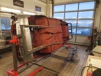
Reworks
The main area of rework ist the complete underbody. With the help of a turning device, life is a lot easier. Welding rework, final grinding and brushing and adding anti corrosion primer is the main job. Another last sheet metal work ist the revision of a usual sin of the 70s: Closing roughly made openings for speakers in package tray :-)
Repair of Doors
Both LHS and RHS doors come from a donor OSI and are looking quite good compared to all aother doors I have seen so far. Quite good means minor corrosion damage LHS and repair of both oter and inner panel RHS. Joining of the outer surface ist made without adding material and welded by WIG welding process.
Tinning
Almost all Joining Areas of the outer surface have to be equalized by tinning to balance the poor stamping and joining quality. As in original OSI manufacturing plant also every gap between body and doors, bonnet and hood are build by tinning. Lots of hours of manual hand made surfaces later, the result is almost perfect gaps and fit and finish.
Thousand little things
Thousend little thing towards the final finish after a long long journey. Very keen to see you again painted and assembled !!